The Counting Box

My son—now four, but three when I conceived this project—loves numbers and counting. More than a few times I’ve peeked in at night to find him asleep with a calculator in one hand and a flashlight in the other. And one of his favorite things to do with the calculator is incrementing “1 + = = = = = = = = = =” until he can’t keep his eyes open any more. I decided to build him a dedicated machine that would do nothing but count up and count down.
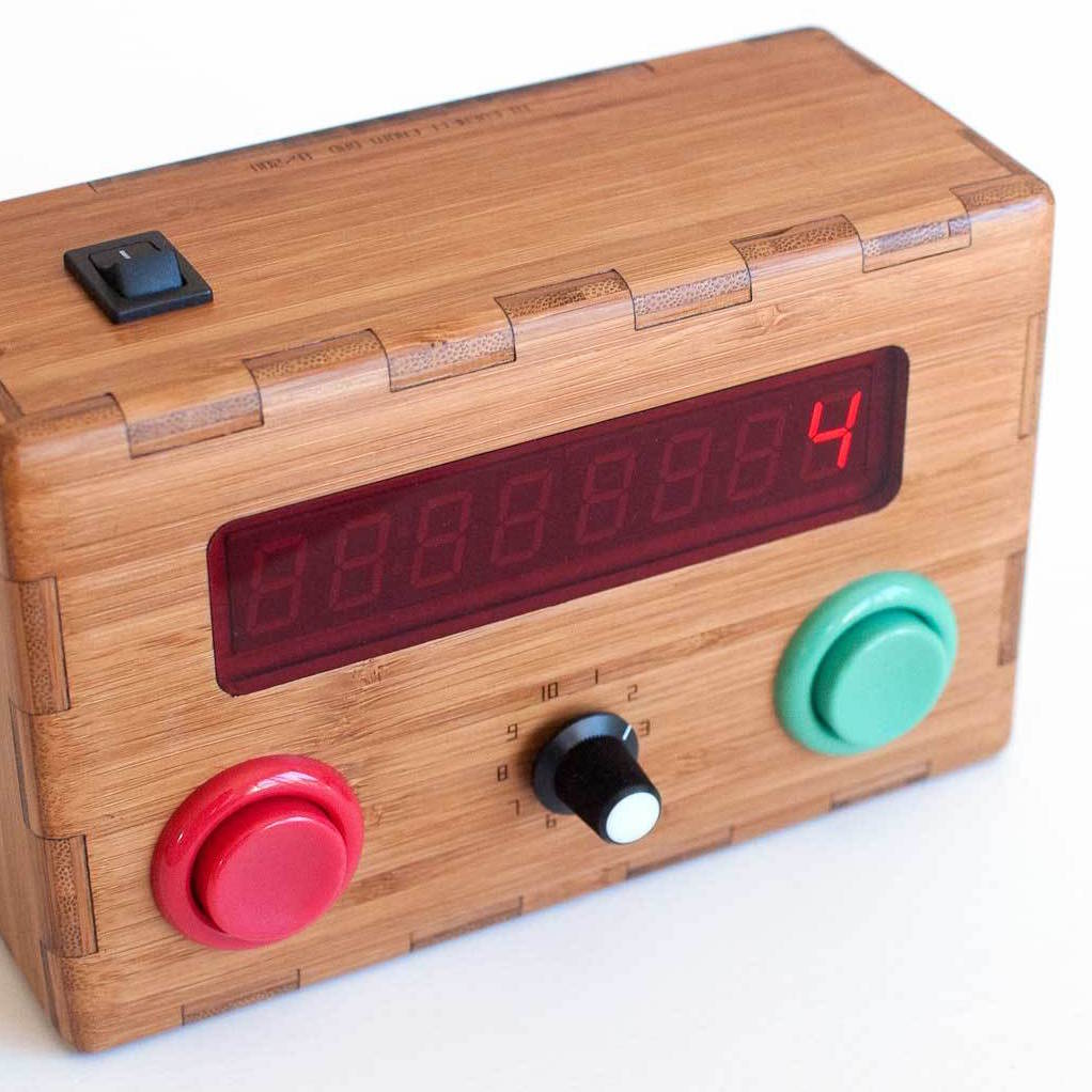
My initial concept was simple: a seven segment LED display so it could be read in the dark, a rotary switch in the middle to choose the value to operate with, and big buttons for adding and subtracting. Green makes the number get larger and red makes the number get smaller.
Below is the finished product. Click the “Continue Reading” link under the picture for details about the process of building and programming. I didn’t take a lot of photos through the build process because there wasn’t much to see, so I’ll illustrate relevant parts of the writeup with photos of the finished counting box. Also, please be aware that this is meant more as a documentation of my build process and the things I learned, rather than as a step-by-step how-to guide to make your own. I hope you’re still able to learn something or be inspired.

The Circuit
The electronics were first, since the size of the case would depend on the size of the finished electronics. I ordered these 4-digit seven-segment displays and this 10-position rotary switch from Mouser, and these video game buttons from Sparkfun. It would all be driven by a standalone ATMega 328 on a perf board. I wanted a big display, lots of numbers, and sturdy buttons. Miniaturization was not on the priority list.

The basic circuit was pretty easy to breadboard and program, but oh that confusion the first time I set the dial to 1 and pushed the increment button, only to watch the display whizz right up into the two-hundreds. Not so nice to meet you, switch bounch.
If you don’t know—and I didn’t—switch bounce is the electronic noise or chatter on the millisecond level as a switch’s contacts open or close. What seems like one button push to us can be read by a microprocessor as dozens, hundreds, or more. Days of research followed on the best way to deal with it (a function known as debouncing): hardware or software, SR latch or RC? My head was swimming.
Fortuitously, the buttons I ordered happened to be double-throw switches, allowing me a fairly simple debounce solution in hardware with two NAND gates for each switch, using a 74HC00 integrated circuit with four such gates. The debouncing explanation at robotroom.com guided me well through the process. I still can’t completely wrap my head around it, but it works.
The astute among you may have noticed, if you clicked the link above, that the rotary switch was complement coded. I had no idea there was such a thing, but the end result is that that “on” should be measured as “off” and “off” as “on” when processing the output. An output of 1110, instead of being read as decimal value 14, was really 1. It was a learning experience as I worked around it in the code, and something else to watch for next time I order parts.
I also needed a way to store the current value of the display. One of my goals was to not have the display reset whenever the power was turned off, because this shortcoming of calculators has led to a few tears in the number-loving boy, and I could do better. This should be an easy job for the ATMega’s internal EEPROM, but when I started looking it was only rated for 100,000 write cycles. With a display that could go up to 99,999,999, that didn’t seem good. Instead I found the 24LC256 2-wire serial EEPROM, with 1,000,000 write cycles.
The display is driven by a MAX7219 chip, which can drive 64 LEDs or 8 seven-segment digits with only 3 output pins on the ATMega. Interfacing with this was easy, with the only difficulty coming from keeping track of which wire was which when linking to the LEDs. Counting up to 99,999,999 might take a while, but it’s good to have goals, right? The real reason I went that high was only because I didn’t want to wire up individual LED displays to make a seven digit display, and two 4-digit displays was a good fit for the box size I was working toward. Design-wise, the edge of the display lines up with the vertical centerline of each button, and the distance between the buttons is dictated by the size of the circuit board that fits between them.
I put it all together on a Radio Shack perf board, which later had to be trimmed to fit the finished box. The LED displays are on another larger perf board connected by ribbon cable to the main board. For the first ribbon cable I used an old hard drive cable, but by the time I did the second I’d picked up some rainbow colored ribbon cable. I didn’t feel like re-doing the first so I left it gray. The display perf board also needed some material removed where the buttons went, and the roller on the belt sander gave it just the right radius.
One big change right at the end was that my original concept had two sets of three AA batteries in series, feeding in parallel into a 5v step-up circuit. After putting together the wooden case and playing with it, I realized what a pain it was going to be to swap out and charge all those batteries, so instead I ordered a 3.7V 6600mAh (overkill, I’m sure, but better overpowered than underpowered, right?) lithium ion battery pack from Adafruit and a Li-Ion USB charger to go with it. Those feed into the step-up circuit, which provides the 5V the system needs.
The picture below shows the finished circuit right before I mounted it into the box.

The Software
I don’t want to fill up this post with all almost-500 lines of it, but you can take a look at the code here. Between my comments in the code and my discussion below, you might be able to make some sense of it.
There are 3 main things the code needed to do: display numbers, handle button pushes and incrementing/decrementing a variable, and finally storing that variable to memory.
The number display is handled by the LedControl library driving the MAX7219. One challenge I had was figuring out how to split the number variable into its component digits. The modulo operator provided the answer, by successively finding the remainder of the value divided by 10 and storing it to an array, then dividing the number by 10 to move on to the next digit. Let’s take the integer 982, for example. 982 mod 10 (in other words, the remainder of 982/10) is 2. That means 2 will be the digit in the ones place. Now 982/10 = 98 (it’s an integer, so there’s no .2). 98 mod 2 = 8. So 8 will be the digit in the tens place. 98/10 = 9. Since that’s the last one, we don’t need to find the remainder.
Button pushes come through as interrupts, which do pretty much what it sounds like they would—they interrupt any other actions taking place in the program when a condition changes, in this case the status of the button. The other alternative is to constantly poll the button to see if it’s being pressed, but this is inefficient compared to essentially asking the button to let you know when it’s being pressed.
The functions that handle the interrupts first check to see which mode the system is in, then acts accordingly. There are three basic modes: NORMAL mode (mode value 0), DELETE mode (mode value -1), and STATS mode (mode values 1-4). If the system is in normal mode, the interrupt handler calls a function to read the rotary switch and decode it, reset the idle timer, and then it adds or subtracts the value indicated by the switch. If it’s in DELETE mode, pushing the decrement button confirms the delete and resets the counter to zero, while pushing the increment button cancels out of DELETE mode into NORMAL mode. In STATS mode, pushing the increment button display the next statistic.
Memory is handled by the I2C example from Arduino Playground, with unnecessary stuff cleared out. In every loop, the program compares the current value of the variable to the value of the variable on the previous loop. If they’re different it stores the new value to memory.
The statistics feature I mentioned before stores the highest value reached, the lowest value reached, and the total number of button pushes for each button. This secret stats mode can be accessed by setting the rotary switch value to 3 and holding down the green button on startup. The setup() function checks for that condition and if it exists, sets the “mode” variable to 1. The loop that displays values sees this and displays the appropriate statistic. With each button push after that the increment() function advances the “mode” variable, and the display updates accordingly. This should make for some fun revelations in a few months or years.
My original circuit plan had a zero-switch reachable with a paperclip through a hole in the case, so it wouldn’t be accidentally bumped. I wasn’t quite sure where the circuit was going to fit into the case so I decided to drill it myself rather than having it laser-cut. It’s a good thing I took that route because after writing the stats code I decided to handle zeroing numbers the same way in software, not hardware. So, if you the set the rotary switch to 8 & hold down the red button on startup, it’ll ask you to confirm you really want to reset, then take the current value back to zero. I haven’t told my son about this yet; it’s more fun to watch him work on his subtraction when he wants to get back down to zero. “If you have 16, what’s the fastest way to get to zero? 10 and 6? How else could you do it?”
To save a little bit of power, the ATMega and the LED go to sleep if no buttons are pushed for one minute. Pushing either button will wake it again without incrementing or decrementing, then return control back to the regular interrupts.
I don’t feel like I optimized the code as much as I could have, but then again there’s not a lot of point to doing so other than geek pride. It works, and that’s what matters.
Construction
I designed the case in Adobe Illustrator and planned to have it laser cut from bamboo by Ponoko. I’ve used their service before, but never for anything like this that had to fit together so precisely. To make sure it would all fit, I printed the plans, spray-mounted them onto 1/4″ foam core, then cut it out with an X-Acto blade and assembled it. 1/4″ isn’t an exact match for the .264″ bamboo, but it was close enough to tell that I hadn’t made any egregious errors like trying to fit two slots together, or two tabs. Not only did the mockup fit together, but everything fit into it.

Right before I sent my original plans off for cutting, I had a feeling there had to be some easier way to make the joints, and I found a great online utility called BoxMaker to generate a plan with all of the appropriate dimensions for finger joints on a box. Enter the outer width, depth, and height, the thickness of the material, and the kerf width, and out comes a PDF. I made a few minor tweaks to the spacing (for symmetry between left and right sides), placed the elements like the window cutout and button holes, and uploaded it to Ponoko. Here’s what I sent:

And two weeks later, here’s what arrived:

It was beautiful, but to my dismay, the pieces didn’t fit together. I’d specified too wide of a kerf, and in compensating for that the BoxMaker program adjusted the widths of the notches to close up gaps that didn’t exist. The notches were now too tight! It was nothing a little time with some sandpaper couldn’t fix, though, and with my son’s birthday rapidly approaching I didn’t have time to make edits and place a new order. It also turned out that the wood was slightly thicker than specified, so the tabs didn’t reach all the way through the corners. This shortcoming became almost invisible after some careful rounding of the corners to soften them up.
Once the box was glued together, it was time to cut some channels for wires to get from the front of the display board to the back. A router bit chucked into the drill press and plunged repeatedly to a depth stop took care of this. As tempting as it may be, don’t try to use the drill press as a router or milling machine because the bearings aren’t meant for force to be applied laterally. The rotary switch required that some relief be drilled into the wood, otherwise the nut holding it on couldn’t reach the threads. I did this with a Forstner bit in the drill press.
The red acrylic window covering the LEDs was also laser cut by Ponoko. Since I had an entire 7×7″ piece and the window was only about 1×5″, I put six different versions on, each sized a few hundredths differently. If I’d simply used the same shape I used to cut the window out of the bamboo, the width of the kerf would make it loose. I was hoping for a tight fit that wouldn’t require any glue, and one of the sizes (I can’t remember which) was just right.
In another departure from my original plans (it happens a lot), I decided I wanted the back to be removable in case I had to pull something out for repair. There was no way I could get it all out and back in through the battery door like I originally thought I would, so I glued in some corner pieces to screw the back board to rather than gluing it as I did the other edges.
For durability, I used a gloss polyurethane to finish the wood and give it a warm, amber glow.

The final nerve-wracking test… would it be possible to fit everything in?
It was, but just barely!
To hold everything in place I cut and bent an aluminum sheet to use as a shelf, with the battery and voltage converter velcroed onto the front side and the circuit on the back. I drilled and tapped holes into the aluminum to mount the circuit, and of course managed to mangle the threads on one of the holes. Since it wouldn’t be seen, I super-glued a nut on the front side for the bolt to thread into. Adapt and overcome!
The last minute change in power sources also let me do something I’m especially grateful for, and that was to put the circuit facing outward where the AA batteries would have been, allowing the door on the back to serve as a little window to peek at the circuit. My son loves the Snap Circuits kit we share, and one of the first things he did after I gave him the counting box was to open the back and squeal “That’s a capacitor! And that’s a resistor!” Oh, how my nerd heart leapt with joy!
To keep any fingers from pulling out fragile wires, I covered it with a piece of plexi cut to size on the band saw and smoothed on a disc sander, held off the board by standoffs that were cut down to just above the height of the mounted ICs. A few notches had to be made in the plexi for the USB charging port and its screws, but the belt sander made quick work of those.


The door on the back, originally meant to provide access to the batteries, is held on by 3mm neodymium magnets epoxied into holes drilled into the door panel and the frame. To ensure that the magnets on the door were aligned with the magnets on the door frame, I drilled guide holes through a spare piece of wood and used that as a template. The magnets are strong enough to keep the door on through regular use, but they give when pried open by fingers in the half-moon cutouts.

One last charging session, closely watched to be sure nothing burst into flames, and at long last (four months since my first parts order), the counting box was done. After all the work it was nearly impossible not to play with it myself, but I didn’t want to affect the stats it was primed to store.
The project was a lot of work over a lot of late nights, and pushed me to learn things I didn’t know about electronics, coding, and woodworking. Yeah, it’s just a silly box with some buttons, but my payoff for all of it is evident below. Somebody is pretty excited that they got all the way up to 1060.

Leave a comment
Comments will be approved before showing up.
Also in Projects

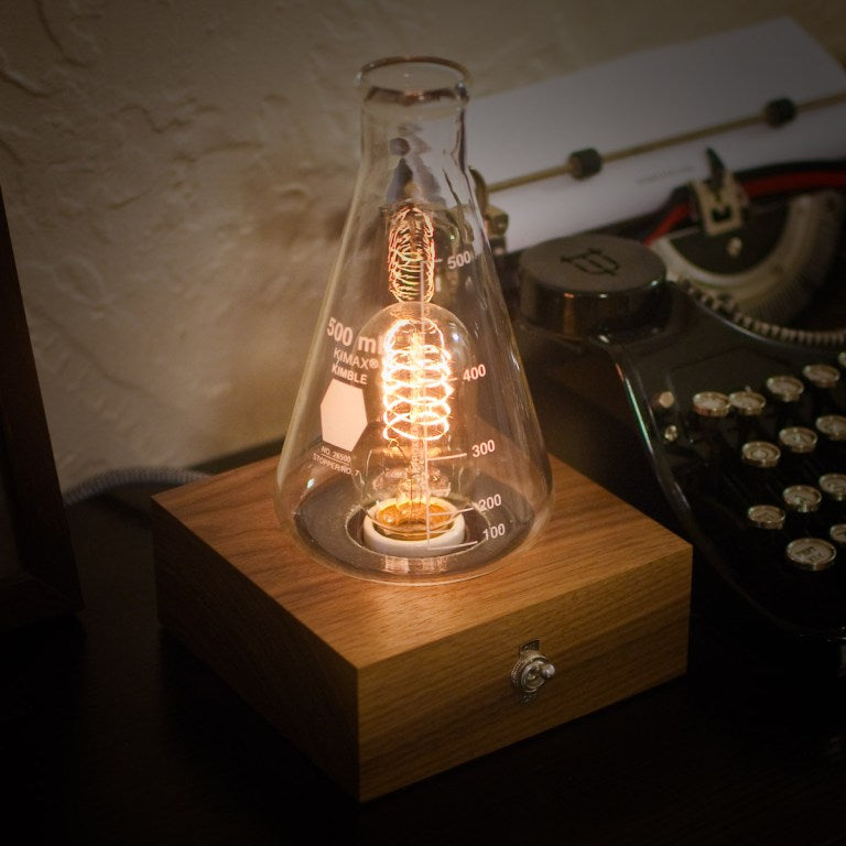
The Laboratory Lamp
First created in 1860, the Erlenmeyer flask has come to symbolize chemistry, and by extension science as a whole. I wanted to use that symbol to create an item of functional decor, and what better for that than a lamp, with the relationship between the light bulb and the “aha!” of an idea?


Garbage In, Garbage Out
For over a decade I’ve had kicking around in my garage’s attic the cases from a couple of old original-style Macintoshes, waiting for just the right project.
One day, after staring at them stacked in my office, I realized that they had a similar form factor to the classic bullet-top garbage cans with the swinging lid. I could give one of these a new (slightly unceremonious) life as a garbage can!

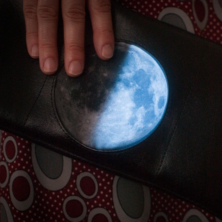
Moon Phase Purse
I’ve been going through a moon phase recently (pun absolutely intended), and thought it would be fun to make a wearable or totable that displayed the current state of the moon. There would be a bit of hardware involved, so a purse seemed like the perfect vehicle—you’re already carrying a load of other things, so there’s no harm in the addition of a small battery pack or a pile of LEDs.