Pumpktris


What do you get when you combine a pumpkin with the classic video game Tetris? Pumpktris! Fully playable, embedded in a pumpkin, and with the stem serving as a controller. Watch the video below to see it in action, then read on for the development story.

The Idea
One of my habits is to write down all the crazy, fleeting ideas I have, then go back to review later rather than judging right off the bat, or even worse, forgetting them. Earlier in the month I was looking through that idea notepad and found “Make Tetris Pumpkins” from sometime last year. My original plan had been to make forms to shape pumpkins into Tetris pieces as they grew, then stack them together for Halloween. Since Halloween was only a few weeks away and it was too late to start growing pumpkins, I thought “Why not make a pumpkin you can play Tetris on instead?”
I had a LOLShield I hadn’t assembled yet, and I knew that someone had already written Tetris for it, so I figured it would be a simple matter to poke some holes in the pumpkin to match the LEDs, make a controller, and be done. But oh no, that would be too simple, and would look kind of lame. Little tiny LEDs, all stuck together on a 2×3″ area? Nahhhh.
Plan B: Still use the LOLshield, but instead of mounting LEDs in the shield I would wire them up externally so I could space them out more on the pumpkin. Luckily, I didn’t get too far down that route before I realized that the bundle of wires between the LEDs and the shield would be as thick as my wrist and a nightmare to solder and organize.
I was going to have to make my own LED matrix and program my own Tetris. With the decision made, I ordered 140 amber LEDs from Mouser and a pair of LED Matrix I2C “backpacks” from Adafruit. These little circuits come with a mini (.8″ square) LED matrix that I could use for programming instead of having to wire up my own LED matrix right from the start..
Time to Solder
The first step was to make the LED matrix, and for that I’m grateful to have found this guide on hackaday.com to making a 70 LED matrix. My construction steps were essentially the same (plus 58 more LEDs), but I’ll go through them here anyway. For more theory, check out their post. Mine leans toward “what I did” rather than “why you should do it this way.”
It started with cutting 112 pieces of 2.5″ wire and 16 pieces of 8″ wire. The short ones would go between each LED, and the long ones would run to the controller. A cutting mat made it easy to quickly and accurately measure out the lengths.

Next I soldered seven short wires and one long one into a daisy chain. Then again 15 more times—one for each row and one for each column in the matrix.

A jig was needed for assembly, and here I differed from Hackaday. Instead of drilling hardboard, I opted to poke holes into 1/4″ foam-core board with an awl. It was a lot quicker than a drill would be, and the foam-core board had a little bit of give so that I could make the holes small and they’d stretch out to hold the LED securely while I soldered.

With a row of LEDS poked into holes, I tinned the base of each anode and clipped it short, then soldered the wire daisy-chain down the line. At each joint I slipped on a half-inch of heat-shrink tubing before soldering. I’m proud to say there were only a couple of times I forgot the heat-shrink and had to go back. What caused more trouble was being in a hurry and sliding the tubing down to the joint while it was still hot. It would start to shrink up and wouldn’t fit over the connection on the LEDs.

When eight rows of LEDs were finally strung together, it was time to mount them all into the jig and solder on the cathode columns. The procedure with the heat-shrink was the same. As each column was finished I would pull it out of the jig and fold it out of the way in order to reach the next column.

Check it out! A finished LED matrix!

But guess what? That’s only one, and 8×8 isn’t enough room for a game of Tetris, so it all got done again! I’ll spare you a rerun on the pictures and description, but if you want to you can go back up and read it again to get the full experience.
The Adafruit LED Matrix Backpack is meant to have its LED matrix soldered right to the board, but instead I soldered on female headers that would permit me to plug in either the mini LED matrix for code testing or the large matrix for deployment. Someone will probably be along to tell me I need a resistor here or there or I’m going to blow some chip up—and they’re likely right—but it seems to have worked so far as-is.
To connect my own matrix to the I2C Backpack, I cut down a piece of prototyping board and soldered in the male headers, then connected the 8″ wires from the last row and last column of the matrix to the board.

Would it work, though? I needed some code in order to find out.
Code
I did all coding with the hardware mounted on my bamboo prototyping board. The mini matrices in the I2C backpack sockets fit on the desk much better than the big, floppy matrices I built would have.

There are seven Tetrominos—yes, that’s what they’re called—in the game. Each has four points, as implied by the “tetra” prefix. A three-dimensional array stores the location of every pixel of every shape, in each of four possible rotations. Storing each rotation is a lot easier (for my brain at least) than calculating it on the fly. As an example, here’s the T shape:
/* T */ {
 /* angle 0 */ { {0,1}, {1,1}, {2,1}, {1,2} },
 /* angle 90 */ { {1,0}, {1,1}, {2,1}, {1,2} },
 /* angle 180 */ { {1,0}, {0,1}, {1,1}, {2,1} },
 /* angle 270 */ { {1,0}, {0,1}, {1,1}, {1,2} }
 }
To draw the active piece the program keeps an activePiece variable (the index of the shape in the array) and a rotation variable (the index of the rotation description of that shape), then offsets each pixel pair that it pulls out by a yOffset and xOffset of how far down the screen it’s moved and how far left or right.
It also keeps an array describing the status of each “fixed” piece. With every move of the active piece, whether by gravity or by user control, it checks against that fixed-piece array to see if the requested move can be made without a collision. If the forbidden movement is left, right, or a rotation, it simply doesn’t make the move. If the forbidden movement is vertical it considers the piece to have landed and writes the piece to the array of fixed pieces, then launches a new active piece. Along the way it keeps score, tracks the level, speeds up the drop of the active piece as the game goes on, etc.
You can download a copy of the code here. In order to use it you’ll also need to download the Adafruit LED Backpack library and Adafruit GFX libraries and install them on your computer by copying each to the “libraries” folder of your computer’s Arduino sketch folder.
The Wet Work
This project required the perfect arcade cabinet—errr, I mean pumpkin. It had to be tall enough that the eight-inch tall matrix wouldn’t wrap too far around the bottom or top, and it needed a nice straight stem. I bought 3 pumpkins in a row, thinking each was perfect until I got it home and realized one thing or another wouldn’t work. Finally I found what I needed and the other pumpkins were relegated to prototyping duty for practice drilling holes and cutting.
To get inside the pumpkin I cut a large opening on the back. It wouldn’t work to cut from the top because I wanted the controller up there, and it would be easier to put the LEDs straight in from the back rather than the top.
With a paper template taped on to the pumpkin, I poked guide holes through the orange flesh.

Once the holes were marked I drilled through with a 13/64″ bit.

And since round pixels just would not do for a proper Tetris game, I cut a square around each hole with an X-Acto blade. The ends of the holes on the inside of the pumpkin were left round.
![]()
To turn the stem into a joystick I carefully sawed the it off at its base and drilled a 1-1/8″ hole right where the shaft would pass through.

I squared off the inside of the pumpkin below the stem, cut down some drywall anchors so they wouldn’t poke through the pumpkin, and screwed them in. Later I would attach the joystick with short screws into the drywall anchors.

For a controller I used short handle joystick from SparkFun, with the red ball unscrewed and replaced with the stem of the pumpkin. I think I’m going to call this the “joystem” from now on, as disgusting as that may sound. I drilled a hole in the detached stem and epoxied in a 6mm bolt, then screwed that into a coupling nut on the joystick shaft.

One at a time, I started to poke each LED into its slimy place. It wasn’t long before a problem became apparent: there were 16 rows of holes on the outside, but only 15 on the inside. The angle that the holes were drilled toward the top of the pumpkin had the two rows coming together into a single row. I was eventually able to squeeze the LEDs past each other and direct them into their appropriate shafts. Once the LEDs were in, I attached the joystem.

I plugged each matrix into the I2C backpack and then that into the Arduino. Usually I’ll build a standalone bare-bones controller board, but since this was definitely not a permanent piece I used the Arduino board. Power was provided by eight rechargeable AA batteries.
It was time to play Pumpktris!

Everything worked great, except for some occasional glitches in the top matrix as the night went on. Maybe a power supply issue, but it’s also possible there might be some intermittent shorts that happen when you bury that many electrical connections inside a pumpkin. It’s also weird playing with the controller on the top and the display underneath, so if I were to do it again I would wire the joystem into a separate pumpkin, either wireless or with the wire made to look like a vine.
Next up? Porting Halo to a watermelon.*
By the numbers:
- 128 LEDs
- 256 pieces of heat-shrink tubing
- 313 solder joints
- around twelve hours of work over a week and a half
- 9800-point high score so far
* No, not really.
UPDATE: I did a more in-depth writeup on how to make your own (as opposed to this story about how I made mine) at Instructables.
Leave a comment
Comments will be approved before showing up.
Also in Projects

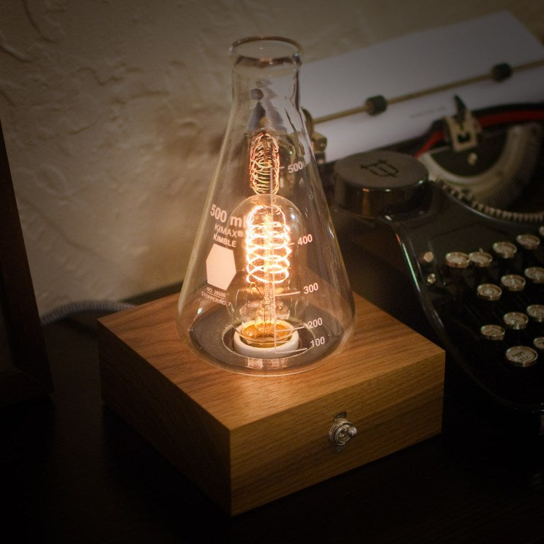
The Laboratory Lamp
First created in 1860, the Erlenmeyer flask has come to symbolize chemistry, and by extension science as a whole. I wanted to use that symbol to create an item of functional decor, and what better for that than a lamp, with the relationship between the light bulb and the “aha!” of an idea?


Garbage In, Garbage Out
For over a decade I’ve had kicking around in my garage’s attic the cases from a couple of old original-style Macintoshes, waiting for just the right project.
One day, after staring at them stacked in my office, I realized that they had a similar form factor to the classic bullet-top garbage cans with the swinging lid. I could give one of these a new (slightly unceremonious) life as a garbage can!

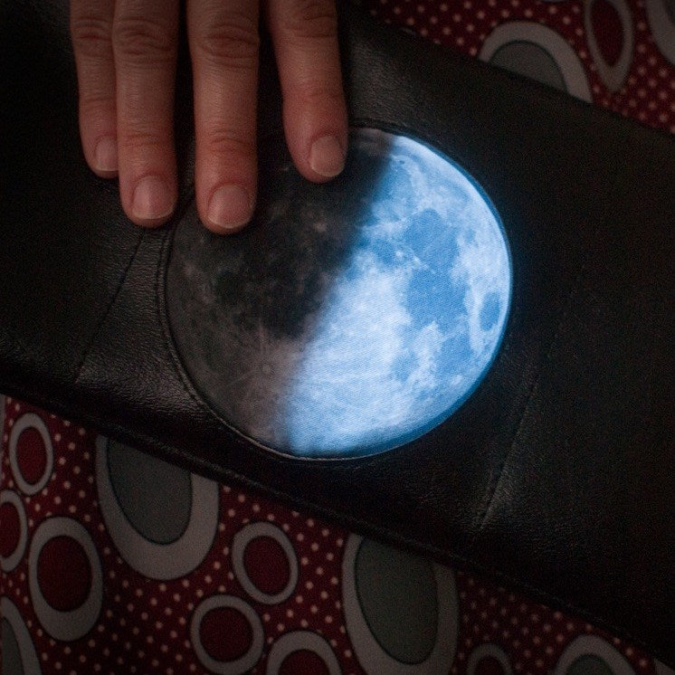
Moon Phase Purse
I’ve been going through a moon phase recently (pun absolutely intended), and thought it would be fun to make a wearable or totable that displayed the current state of the moon. There would be a bit of hardware involved, so a purse seemed like the perfect vehicle—you’re already carrying a load of other things, so there’s no harm in the addition of a small battery pack or a pile of LEDs.